Alternative Process Tutorials

Alternative Process Tutorial #11
Building a UV Light Bank
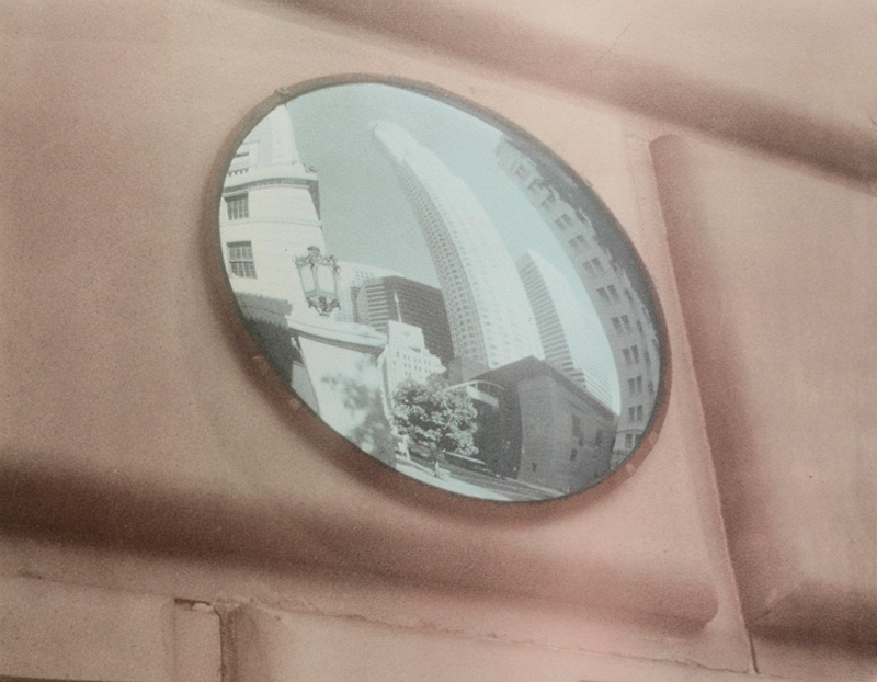
Illustration #91: Gum Photograph
Copyright © 1995 by Tom Ferguson
Click on image for larger view
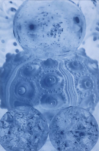
Illustration #92: Cyanotype Photograph
Copyright © 2000 by Tom Ferguson
Click on image for larger view
This tutorial is optional. Many alt printers work happily in the sunshine and outdoors!
Most alternative processes are highly sensitive to blue and ultra violet light, and quite insensitive to the yellow and red light. Two of the best sources of blue and ultra violet light are the sun and certain fluorescent lights. Unfortunately the sun varies in intensity due to time of day, time of year, haze, or pollution levels. Pollution... can you tell I live in Southern California? If you continue with alternative process work, you may want to build a bank of UV fluorescent lights. This will allow you to work indoors and is both more convenient and consistent than sun printing. These instructions are for a unit large enough to print 11x14 (or 8x10 or 4x5) negatives. The project can be sized up or down to suit your needs (different sized and powered bulbs may then be needed). All sizes and materials are in USA measurements. For the rest of the (metric) world, you will need to do some converting.
While all fluorescent bulbs emit some UV light, the "F15T8/BL" series bulbs are specifically designed for it. These are not the black lights used for posters. They are white frosted bulbs that look like a conventional household fluorescent bulbs. They are made by GTE and Sylvania, and can be obtained at most good lighting shops (see materials and sources page). You will also need fixtures for these bulbs. Most hardware stores will have wall or ceiling mountable individual fixtures for 18" (15 watt) fluorescent bulbs. Make sure that these fixtures are not longer than 22 inches.
Buy the Materials listed in illustration #93. Use a jig saw, or bare saw blade, to remove any diffusion panels from the fluorescent fixtures. You want the bulb to be completely exposed. Next, measure the height of your fixtures with a bulb installed. Also measure the height of your contact frame. Add these numbers together, then add another 2-1/2 inches. As an example if your fixtures are 1-3/4 inches and your contact frame 1-1/4 inches, then your total would be 1-3/4 plus 1-1/4 equals 3 plus 2-1/2 equals 5-1/2 inches. Use this number as "Total Height" in illustration #94.
| Illustration #93: Materials List | Illustration #94: Cut Pieces |
UV LIGHT SOURCE PARTS LIST |
CUT PLYWOOD CUT 2x2 WOOD |
Cut all the wood pieces listed in illustration #94. Paint all pieces flat white (not glossy) and allow to dry. Drill a 1 inch hole in the top piece centered front to back and 2-1/2 inches from one side . This will be used to pass the electrical cords through. Using a pencil, lightly mark lines 2-1/2 inches from all sides of the "top" piece. You should now have a penciled "box" of about 22x12 inches centered on your top piece (see illustration #95). Now attach with #6 x 1/2" screws (or with contact cement) your 6 light fixtures (with bulbs removed). Arrange them so that they are center and equally spaced within the penciled square. Place the fixtures so that all of the electrical cords face the side of the top with the drill one inch hole. Pull the electrical cords through the hole to the opposite side of the top. Most brand's AC plugs will not fit through this 1 inch hole. Cut off the AC plug and simply pull the wire's ends through the hole.
Assemble the unit as shown in Illustration #96 using #8 x 1-1/2" screws. The two 2x2 legs go in the back corners, where the plywood back and sides meet. Now install your type "BL" bulbs.
Attach the multi-plug strip to the unit's top and plug in all the fixtures. If you had to cut off the original AC plugs, replace them now. The amount of UV light put out by these bulbs is bad for your eyes, and can cause headaches. Next, glue the black cloth across the open front, this will block most of the UV light from spilling into your room. Illustration #97 shows the completed unit. Due to the large current spike needed to turn on these bulbs, any timer used should be rated for at least 360 watts (actual rating of the bulbs times 4).
Notice that I have left one plug free on the "7 outlet multi-plug AC strip". If you do a lot of gum printing, you may want to add an exhaust fan to the rear of your UV light unit. Gum prints are damaged by heat.
Your UV light bank is now ready to use, although you will need to retest for your process's MBT and "target zone 8" (see tutorials 8 to 10).
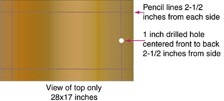
Illustration #95: Top Assembly Diagram
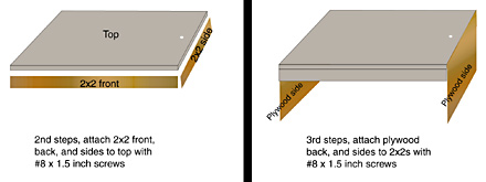
Illustration #96: Full Assembly Diagram

Illustration #97: Finished unit
Click the "next" button below and we will start palladium and platinum printing instructions.
< Previous Page (MBT) | Lessons Table of Contents | Materials Page | Next Page (Platinum) >